Why Thrusters?
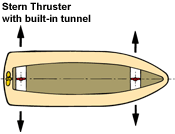
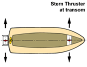
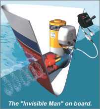
It is extremely difficult to control the movements of a boat as it is slowing to a halt, especially in the bow area. Bow thrusters can correct this situation by applying a lateral thrust at the bow of the boat. Even when the boat lies dead in the water, it is possible to maintain complete control of the movements of the ship's bow by operating the bow thruster. Stern thrusters allow the helmsman the opportunity to fine tune his approach for perfect dockage.
Selecting the Correct Bow Thruster

The force applied by the wind onto the boat is determined by the factors: wind speed, angle of wind attack and lateral wind draft area of the boat.
The Wind Pressure
- When the wind speed increases, the wind pressure increases quadratically!
- For wind pressure 'P', the formula reads: P = 1/2p × V² (l bf/sq.ft)
- p (rho) represents the specific mass of air and 'V' stands for the velocity of the air in ft/s.
- The table below will give you an impression of wind speeds and the resulting wind pressures.
It will not be possible to counter completely the adverse effect of winds of 40 knots or more. But, in such cases, the bow thruster will still "lend a strong helping hand".
The Wind-Draft of the Boat
-
The forces applied by the wind onto the boat can be determined by multiplying the wind pressure by the wind draft area. The wind draft area is determined by the shape and the dimensions of the superstructure. Also the wind angle is playing its part. The worst situation is created if the wind is at 90 degrees to the boat. However, due to the shape of the superstructure, which is mostly more or less streamlined, a reduction factor may be applied to the wind draft area, before calculating the wind pressure resulting from the wind speed. This reduction factor may generally be set at 0.75.

The Torque
-
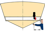
The torque is determined by multiplying the wind force by the distance (A) between the center of effort*
of the wind and the center of rotation** of the boat. Assuming that the wind force is amidships and assuming
as well that the boat will tend to turn at the transom, the torque, caused by the wind force, is calculated by
multiplying the wind force by half of the boat's length.
- Dependent upon the shape of the boat's superstructure, the center of effort may be positioned more forward or more aft.
- The center of rotation of the boat may be positioned more forward, dependent upon the shape of the underwater section.
The Thrust Force
-
The bow thruster is required to apply a countering thrust force, which is at least equal to the thrust force applied by the wind. The required thrust force of the bow thruster may now be calculated by dividing the torque by the distance (B) between the center of the bow thruster and the pivot point of the boat.

Wind Speed - Wind Pressure Chart:
| Wind Speed - knots | Description | Wind Speed - ft/s | Wind pressure - lbf/sqft |
|---|---|---|---|
| 10 - 16 | moderate breeze | 17 - 27 | 0.40 - 1 |
| 16 - 22 | fresh breeze | 27 - 37 | 1 - 1.9 |
| 22 - 28 | strong breeze | 37 - 47 | 1.9 - 3.1 |
| 28 - 34 | near breeze | 47 - 57 | 3.1 - 4.6 |
| 34 - 40 | gale | 57 - 67 | 4.6 - 6.3 |
Calculation example:
|
The boat has an overall length of 36 ft and the lateral wind draft measures 190 sq.ft. It is required that the bow can still be controlled easily when a wind force of 20 knots applies. At a wind force of 20 knots, the wind pressure is: p = 1.0 to 1.9 lbf/sq.ft i.e.p. (average) 1.45 lbf/sq.ft. The required torque reads:T = windpressure x wind draft x reduction factor x distance center of effort to pivot point, (=appr. half the ship's length) T = 1.45 lbf/sq.ft x 190 sq/ft x 0,75 x 36 ft/2 = 3719 ft.lbs. The required Thrust Force is calculated as follows:
The VETUS bow thruster which is most suitable for this particular vessel is the 121 lbf model. Always bear in mind that the effective performance of a bow thruster will vary with each particular boat, as the displacement, the shape of the underwater section and the positioning of the bow thruster will always be variable factor. |
Points to Consider in Selecting the Correct Bow Thruster

The Propeller
-
VETUS applies plastic propellers, which cannot corrode. Due to their low weight, the maximum thrust force is obtained very quickly and with minimum use of energy. The propeller blades are shaped in such a way, that the thrust is equal to both sides. They are also designed with a special view to being used inside a tunnel, thus avoiding cavitation(=unwanted noise!).
The Tunnel
-
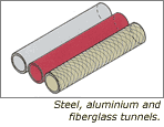
The smaller the diameter of the tunnel, the less resistance it will cause to the boat when under way. Moreover, a smaller diameter also allows for a more forward installation into the bow, which enhances the turning moment of the boat. VETUS has obtained the optimum compromise between high efficiency of the bow thruster and little resistance when the boat is under way. For vessels made of steel, aluminum and fiberglass VETUS offers steel, aluminum or fiberglass tunnels.
The Tailpiece
-
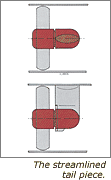
Application of a streamlined tailpiece by VETUS not only ensures a better efficiency through lesser resistance but also a lower noise level. Disturbance of the free flow of water through the tunnel, caused by a non- streamlined tailpiece, results in cavitation or, again, unwanted noise! In order to protect the bronze tailpiece against corrosion by electrolysis, a zinc anode is standard supply with each VETUS bow thruster. The transmission gear inside the tailpiece consists of cogwheels, which produce far less noise than chain transmission.
The Electric Motor
-
In order to ensure the highest possible efficiency, in conjunction with an optimum lifespan, VETUS have solely specified electric motors, which are built to Suit the special purpose of being used as bow thruster motors. Contrary to modified starter motors, the VETUS motors allow for continuous running 'at full throttle' during several minutes.
Installation Possibilities
-
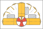
The motor of the VETUS bow thruster may be installed in any position i.e. horizontally as well as vertically. The motor is positioned above the propeller at all times.
What factors will affect the thrust efficiency?
The nominal thrust force can only be obtained under optimum conditions and the following factors will influence the efficiency in a negative sense:
- Low voltage of the power supply to the motor, due to a too low battery voltage or a too large a voltage drop through the battery (main supply) cables.
- When the actual tunnel/hull connection is not executed in the best possible way; in other words: the shape of the tunnel openings is a discerning factor.
- When the tunnel openings are provided with grids; also the shape of the grids may cause another reduction of efficiency.
One or Two Propellers?

However, this law of theory is only valid for the lateral thrust in one direction. The opposite direction will produce a lower performance by the same percentage and, ultimately, nothing is gained. Furthermore, to manufacture a bow thruster with two propellers faces quite a few obstacles, both technically and price wise:
- Two propellers, rotating in the same direction, will have slightly enhanced performance if the "downstream" propeller turns much faster than the "upstream" one, or if it has a larger pitch. But, given the fact that a bow thruster should operate in two directions, this requirement is completely unattainable, as it would involve the installation of three electric motors and three drive systems. Even if this were the case, the improvement in performance would be negligible.
- In the situation where two propellers are rotating in opposite directions, again, the "downstream" propeller should have a larger pitch. But, if the sense of rotation is reversed, then the "downstream" propeller becomes the "upstream" one, producing the negative effects, described above.
- Logically, the mass inertia of two propellers is much higher than that of one propeller. This is even more so, if the propellers are not made of light-weight plastics. In other words: the required thrust power comes with a considerable delay.
- The more components that are installed, the costlier the product will be and the more sensitive to failure. Furthermore, two propellers in one tunnel are far less accessible than a single one.
VETUS has come to the conclusion that they will not introduce bow thrusters with two propellers into their range. The performance of VETUS bow thrusters with a single propeller has been calculated and tested with utmost care. Due to the carefully calculated power transmission, the specially constructed electric motors and the exactly dimensioned tunnels of minimum diameter, VETUS bow thrusters provide optimum thrust power per horsepower.
And that is the only thing which really matters with bow thrusters!
Installation Info


